

Tutorial Details
- Program: Adobe Illustrator CS4
- Difficulty: Medium
- Estimated Completion Time: 4 hours
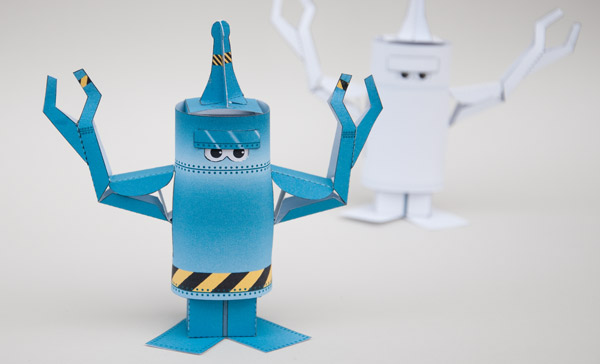
Final Product What You'll Be Creating
This Post is Day 7 of our Character Illustration Session. Creative Sessions
Step 1
The robot model is ready to download as a three page file. Everyone can download the source files for this project and follow along. Page one is used to print the first sheet of robot parts, page two and three are the front and back of the second sheet. Before you print out the model it is time to get creative by adding some color and artwork to the parts. Time to crack open your copy of Illustrator.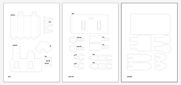
Step 2
The file has three layers: “Names,” “Lines,” and “Color.” Call up the layers window (Windows > Layers ) make sure that the “Name” and “Lines” layers are locked by clicking on the padlock. Click on the Color layer to make it active.
Step 3
All the shapes for the robot are already in place on the “color” layer. They’re white, so you can’t see them yet. Click on them with the Selection Tool (V), then click somewhere in the middle of the Inner Tube shape to select it. Once you’ve selected it, it’ll be outlined as shown here.
Step 4
Change the color of the fill. Open the color window (Window > Color)set the color to C=35, M=0, Y=0, and K=35 as shown below. This is a nice metallic blue, perfect for a paper robot!

Step 5
Set the aerial pieces and outer tube to the same color then change the two thin vertical rectangles to C=0, M=0, Y=0, and K=80. These are the lines that divide the two robot legs.
Step 6
Select all the parts on the second page except the body by Shift-clicking them. Select the Eyedropper Tool then pick up the color from the outer tube. All these parts will now be the same steely blue.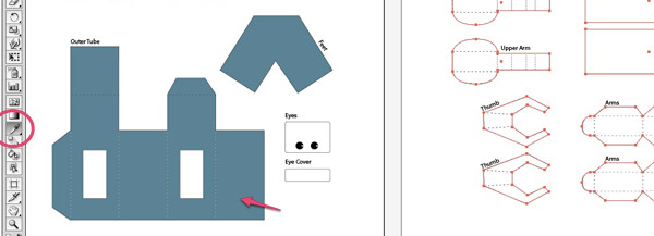
Step 7
Repeat this process on all the shapes on page three. These shapes will appear on the back of the second sheet when you come to print the model out. Notice that they are like inflated versions of the shapes on page two. This is to allow for alignment errors in printing.
Step 8
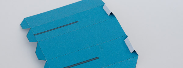
Time to start adding some detail to the body. Select the Pen Tool.Click on one side of the body, hold down Shift to constrain the line horizontally, then click on the other side of the body.

Step 9
Add two more lines by clicking Shift + Alt and dragging the first line.Select all three lines. In the Stroke palette set the line width to 2pt.
In the color palette set the line color to C=70, M=0, Y=0, and K=70.

Step 10
Now press Shift + Alt and drag the lines to create two more lines, one at the top of the body, and one at the bottom.
Step 11
Too make a rivet effect we’ll convert the appropriate lines into dotted lines. Select the top two lines and the bottom two lines. Set the line width of these lines to 3 pt and the end cap style to round. Tick the Dashed Line selection box as shown.
Step 12
The body of the robot is filled with a gradient. Select the body background by clicking on it with the Selection Tool. Open the gradient palette and click on the gradient to fill the robot body with a white to black gradient. We’ll sort out the color and direction in the next steps. Select the Gradient Tool in the tool palette (shown circled).
Step 13
Make sure that you still have the Gradient Tool selected, then Shift + Click-drag from the top of the body to the bottom of the body. Holding down the Shift key whilst dragging ensures that the gradient line is exactly vertical.
Step 14
To give the body some depth we’ll add a slightly more complex gradient than the default. Start by adding some more control points to the gradient guide. Click three times to the right of the gradient control bar on the points shown on the picture. At the moment the gradient will look exactly the same as before, but the three tabs that have appeared are now fixed points along the gradient.
Step 15
To complete the gradient we’ll set the colors at each of the control points. Double-click the top control point and a color palette will appear.Click the button top right of the palette to select the color model and select CMYK.

Step 16
Set the color to C=30, M=0, Y=0, K=30.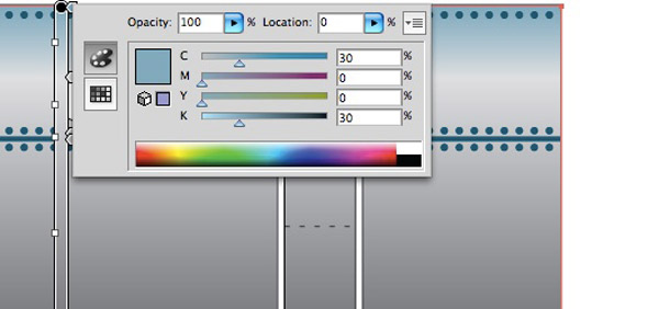
Step 17
Now select the third and fifth gradient control points in turn, and thenset them to the CMYK color model, then to C=30, M=0, Y=0, and K=30.

Step 18
In the same way set the second and forth control points, but set these ones to C=50, M=0, Y=0, and K=50. That completes the gradient for the body. We’ll use the same gradient to give the eye cover a metallic look.
Step 19
Choose the Selection Tool then select the eye cover. Make sure that the gradient swatch (arrowed) is still visible, as you’ll be needing this next.
Step 20
Click the gradient selection swatch with the eye cover still selected. This will put the same gradient as the body into the eye cover as shown below.
Step 21
Select the Gradient Tool from the tool palette, then click and drag in the direction of the arrow to change the angle of the gradient.
Step 22
Next we’ll add some rivets to the feet. Select the Pen Tool. Start at the top left of the foot, click with the Pen Tool to add a control point. Move to each corner of the foot and click to add a line slightly inside the line of the foot. Use the Direct Selection Tool to make corrections, if the line isn’t quite parallel to the edges of the foot. Select this new line with the Selection Tool, then choose the Eye Dropper Tool and pick up the dotted line style from the body (shown circled).
Step 23
Back to the body, we’re going to add yellow and black warning chevrons across the bottom of the body. Set the fill color in the color palette to C=0, M=0, Y=100, and K=0. The stroke color should be unset. Select the Rectangle Tool and drag out a rectangle approximately 5mm by 30mm.
Step 24
With the Selection Tool still chosen, hold down the Shift key, move to one of the corners of the rectangle until the pointer turns into the rotate arrow. Rotate the rectangle by 45 degrees.
Step 25
Select the rectangle then Shift + Alt-drag it to the right so that a copy just touches the original.
Step 26
Select the second rectangle and set the fill color to C=0, M=0, Y=0, and K=100.
Step 27
Now we’re going to make multiple copies of these rectangles to create a chevron effect. Select the two existing rectangles and Shift + Alt-drag them to the right so that the new copy just touches the original. The Shift key keeps everything lined up and level, whilst the Alt key makes a copy rather than just moving the shapes.
Step 28
Repeat this process by pressing Command + D on the keyboard. Press this key combination repeatedly until the chevron is wider than the body part.
Step 29
Now to trim the chevron to size. Make sure that none of the chevron rectangles are selected. Set the stroke color to black and the fill to nothing. Select the Rectangle Tool and drag out a rectangle the full width of the body and approximately 9mm high. Use the snap featureto ensure it exactly fits the width of the body.

Step 30
Drag the rectangle up so that it sits on top of the chevron pattern. There should be no white showing within the rectangle. If there is you’ll need to add a few more bars to the chevron by going back to step 27.
Step 31
Make sure that only the black outline rectangle is selected. We’re going to use the rectangle to cut a chevron border out from the yellow and black rectangles. Click on Objects > Path > Divide Objects Below. The rectangle will disappear leaving the nicely sliced chevron.
Step 32
Select the parts outside the rectangular area and delete them.
Step 33
There will be parts at the top, bottom and at the two ends that you’ll need to delete.
Step 34
Once you have removed all the parts you don’t need you’ll be left with a neat stripy border. Select all of it, and then group it to make it easy to manage. (Command + G).
Step 35
Drag the striped border into position at the bottom of the robot as shown.
Step 36
We’ll make the chevron on the aerial in the same way. Start with a wideband of narrower yellow and black diagonal stripes.

Step 37
Using Rectangle Tool to draw a rectangle over the middle of the aerial. Use the Direct Selection Tool to make it fit the shape of the middle of the aerial.
Step 38
Drag the new shape over the chevron area so that no white is showing.Click on Objects > Path > Divide Objects Below. Delete the
excess bits from round the side. Select all the stripes and group them together.
Step 38
Drag the new shape over the chevron area so that no white is showing.Click on Objects > Path > Divide Objects Below. Delete the
excess bits from round the side. Select all the stripes and group them together.

Step 39
Drag the chevron into position on the aerial.
Step 40
Shift + Alt-drag the chevron onto the two remaining aerial parts. That completes the design for the robot model. There is, of courseonly one possible design. You have a blank canvas, feel free to
make your own designs!

Step 41
Time to print out your robot model. You’ll need some thin cardand a suitable printer. It doesn’t need to be an expensive printer. Most cheap ink jets are up to the job. Make sure that the print options are set to Do Not Scale and that the placement is close to zero. Print out page one and two on separate pages.

Step 42
Flip the second page over and put it back into your printer. Print out page three on the back of the second sheet.
Step 43
Hopefully all the printing will line up. If not, you’ll need to experiment with the values in the Placement or Offset box in your print dialogue box.
Step 44
Set aside the sheets until the ink is completely dry. There are three types of lines on the robot model. Solid black lines show where to cut, you’ll need to cut out some holes as well as cutting out the parts. Dashed lines show hill folds. This is a fold where the line is at the top top of a little hill.Dotted lines show valley folds. They fold upwards so that the dotted line is at the bottom of a valley. To get crisp accurate folds you’ll need to score along all the fold lines before you cut the model out. Line up a ruler with the dotted or dashed line then run the point of an open pair of scissors along the line. You’ll need to experiment with different pairs of scissors until you find a pair that crushes the card rather than cutting it.

Step 45
Use a sharp knife and a cutting mat to cut out the holes in the model.
Step 46
Finally, carefully cut out all the parts using scissors.
Step 47
Time to assemble the model. You’ll need some glue and a glue spreader. The best type of glue to use is PVA – white school glue. Coffee stirring sticks make good glue spreaders.The robot model uses two tubes which slide one inside the other. The inner tube has a couple of triangular stops at the top to limit its movement. Make these stops by folding round the tabs and gluing them
down as shown.
Step 48
Fold round and glue the inner tube together. Be as accurate as possible when lining up the parts.
Step 49
Fold round and glue the tabs on the two stops so that they make triangular pieces, as shown below.
Step 50
Glue the two stops to the side of the inner tube. Line them up carefully with the base and the edge. Notice that they are glued to the sides of the inner tube without the leg divider line.
Step 51
Fold round and glue the outer tube into position round the inner tube. Fold down and glue the top of the outer tube into place. The inner tube needs to be free to move up and down inside the outer tube so make sure there is no glue where it shouldn’t be.
Step 52
Take the body piece and give it a gentle curve by rolling it between your fingers. Glue the body tab into place on the outer body. Check out the picture, you’ll notice that it glues onto one of the sides with the vertical slots. Carefully line up the crease on the body tab with the edge of the outer tube. Let the glue dry completely before the next stage.
Step 53
Roll round the body so that it fits tight round the outer tube. Glue the end down to make a cylindrical body.
Step 54
The two long tabs within the body are used to move the arms up and down as the robot moves. Glue the lower section of the arm tab to the lower face of the triangular stop. Repeat the same process with the other arm tab.
Step 55
Fold the long tab round on the upper arm pieces and glue them down. Notice that the creases are valley folds. The tab folds in on itself. Use the picture as a reference.
Step 56
Glue the triangular piece on the upper arm into place on the inside of the arm. The edge of the triangle indicated with the arrow needs to be aligned with the crease in the arm. Carefully glue the two parts of the claw together so that they are accurately aligned.
Step 57
Fold in half and glue together the thumb piece as shown.
Step 58
Glue the thumb into place on the arm as shown. Repeat these last few steps to make the second arm in exactly the same way.
Step 59
Glue the ends of the arm onto the arm tabs. Line their edges up with the crease indicated by the arrows. Let the glue dry completely.
Step 60
Glue the curved tab on the arm into place on the bottom of the triangular stop piece.
Step 61
Pre-crease the three parts of the aerial as shown in the first picture. Glue the three parts together, lining them up as accurately as possible.
Step 62
Glue the aerial to the top of the head. Let the glue dry completely.
Conclusion
Your robot model is now complete! Hold the feet and pull the body up and down and watch as your robot flexes his paper claws!
This Post is Day 7 of our Illustrative Lettering Session. Creative Sessions
Nenhum comentário:
Postar um comentário